Content will be coming soon (work in progress)
I use a 0.4mm nozzle and at least 20% infill to get good and sturdy results. You will be pressing a lot of buttons on the remote while using it...
1
Clean the knops on the top cover with sanding paper. This is where the display will be held in place. Don't overdo the sanding, since the display will be hold in place only by the friction between the wholes in the circuit board and the knops.
2
Attach the display to the knops. I recommend not removing the display afterwards since the knops can easily fall off.
If something goes wrong here you will need to re-print the top cover.
3
Clean up the rest of the parts especially the holders for the push buttons. You want a clean surface to glue them onto the top cover. There will be some force applied to the joints every time you push one of the buttons. Again, don't overdo the sanding. Otherwise you will have problems fitting the buttons into place.
4
Apply enough superglue to both outer stands of the push button holders. The glue needs to be on the horizontal area and on the outer area that has a 45° angle. Try not to let the glue run into the grooves of the cover.
Avoid glueing together your fingers at that point since it makes it harder to use the remote when it's finished. 😉
Firmly press the holders down so they align with the top cover.
Clamp the push button holders to the top cover and let it cure.
5
Now, put the slide the push buttons into place..
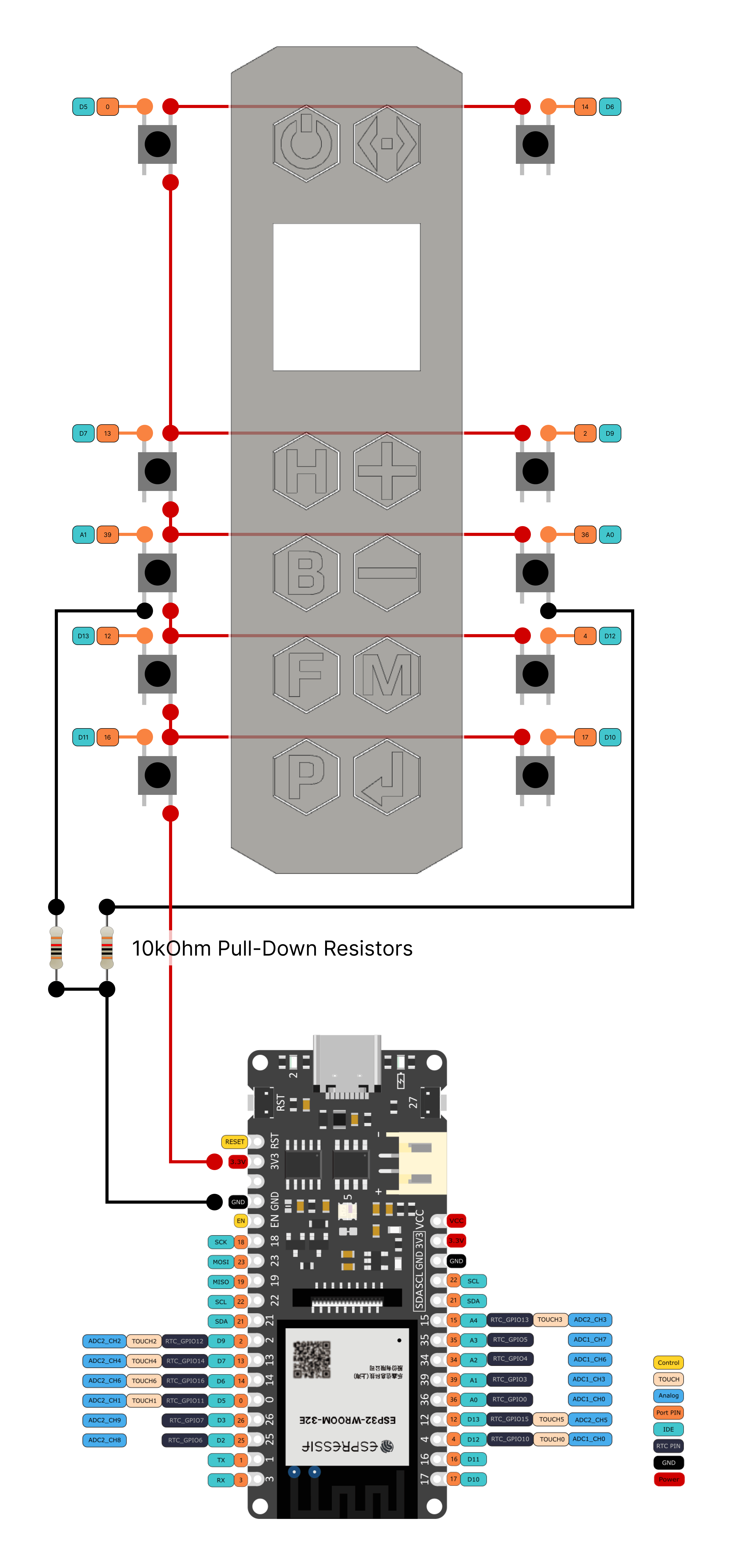
You are now ready for the soldering the buttons to the Firebeetle ESP32-E board. Here is the schematic:
 Note that you will have to include two 10kΩ pull-down resistors for the buttons connected to the analog inputs of the microcontroller. The different ports of the board do different things and we have to reuse two of the analog ports as digital ports. Unlike the other digital ports, these two don't provide internal pull-down resistors.
Connecting the display with the Firebeetle board should be straight forward using the included display connector.
Now you need to download the software to configure and upload the code to the microcontroller. I use the Arduino IDE (download the Arduino IDE).
There are other alternatives, like PlatformIO for Microsoft Visual Studio Code. While I like VSC very much, I find it a bit cumbersome to use it with PlatformIO to code for ESP32 microcontrollers.
Another thing you have to be aware of is that you might need to install the appropriate drivers for the ESP32 microcontroller for your operating system. You can find the latest drivers linked in the FireBeetle 2 ESP32-E product wiki. Make sure to read through the wiki as it holds a lot of interesting information.